

The BT136 triac schematic symbol
In electronics, two of the most important functionalities are the ability to TURN ON and TURN OFF current flow as necessary. These functions justify the large numbers of active electronic components, such as diodes and transistors, that populate many circuit boards. For many applications, simple starting and stopping is insufficient. For example, driving electrical machinery like motors often requires precise control over a wide range of torques or speeds.
Motor control falls under power electronics operations where high voltage and/or current devices are needed. A popular device used for this type of control is the thyristor—a four-layer switch of alternating P-type and N-type substrate materials often referred to as a semiconductor controlled rectifier or SCR. Thyristors and SCRs are unidirectional devices allowing current flow in only one direction. When bidirectional control is required, triacs are used.
In this article, we will discuss triacs, first in general, and then delve into a common type by examining the BT136 datasheet.
Triacs and Their Uses
Diodes conduct or switch on when they are forward-biased or when the voltage from anode-to-cathode exceeds some preset level (approximately 0.7 V is typical for basic diodes), and switch off when the voltage drops below this level or is reverse biased. SCRs operate similarly, except conduction does not start until a gate signal has been applied. Triacs also require a gate signal; however, the signal may be positive or negative, as triacs can conduct in two directions.
Triac Applications
Triacs are used in many applications, including:
- Motor control
- Appliance control
- Electric fan speed control
- Electric light dimmer switches
A common type of triac used in the applications listed above is the BT136-600E, which is described below.
The BT136-600E Triac
The BT136-600E, from WeEn Semiconductors, is a four quadrant, general-purpose triac used for switching and control. Alternate components—such as the L6004F61 from Littlefuse or the T435-600T from STMicroelectronics—do exist. Therefore, you need not worry about electronic component availability when adding this triac to your bill of materials (BOM). When designing with the BT136, it is essential to rely upon its datasheet.
Using the BT136 Datasheet
Features of the BT136-600E, according to the BT136 datasheet:
- Four quadrant triggering
- Low power IC direct triggering
- High voltage blocking
- Low EMI at commutation
- Sensitive gating
- Isolation packaging
Understanding the features above is helpful when deciding whether the BT136 is the best triac for your application. To ensure the best performance, it is essential to know device limitations and maximum ratings, as given in the list of parameters below.
Parametric Analysis of the BT136 Triac
Important parameters for the BT136-600 are maximum voltages, average and peak currents and powers, as well as thermal parameters such as storage and junction temperatures.
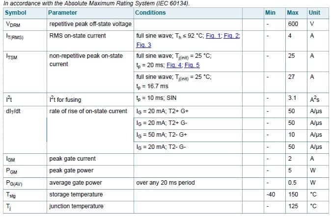
BT136-600E parameter ratings
As shown above, the maximum peak off-state voltage is 600V and the maximum peak operational current is 27 A at a period of 16.67 ms or a frequency of 60Hz. For higher frequencies, the current limit is decreased and the device can handle a continuous 4 A flow with a temperature ≤ 92 °C.
As the BT136-600E is a gate-controlled device, it is also important to ensure your circuit parameters adhere to the static and dynamic characteristics in the table below.
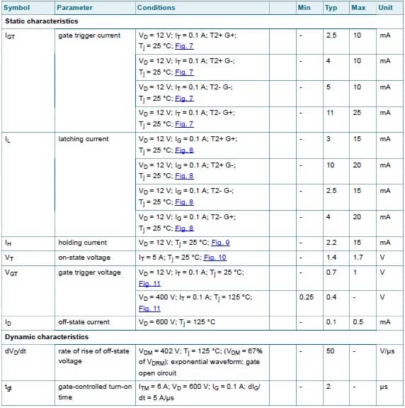
BT136-600E operational characteristics
By consulting the BT136 datasheet, you will be able to properly determine if the device is the best option for your application and design your circuit to meet your performance objectives. However, for PCBA design, additional information not provided in the datasheet is necessary.
Designing Boards with the BT136 Triac
Virtually all datasheets include detailed drawings of the device package(s) that can be used to create or define a component model for laying out your circuit board. This is not the case for the BT136-600E, which uses a 3-prong TO-220 standard “transistor outline” package. For this device and similar through-hole components, there are several landing patterns that can be used. Therefore, you should rely on the footprint dimensions provided in the CAD file, as shown in the figure below.
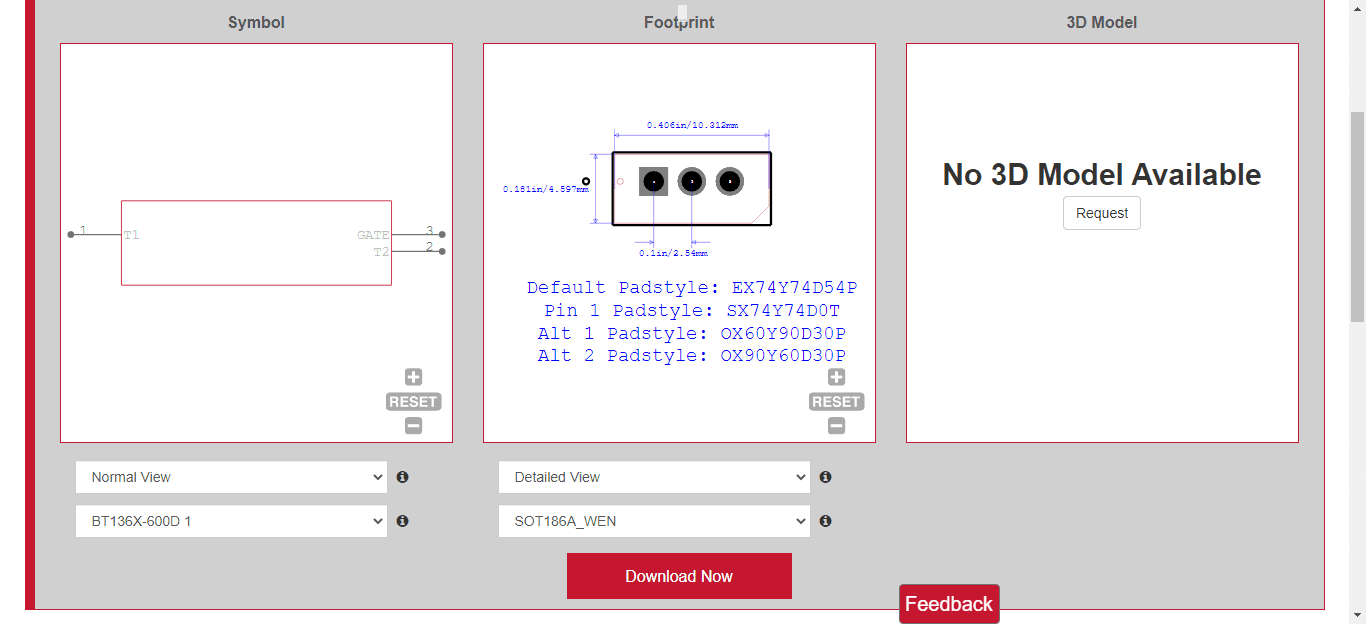
CAD file symbol and footprint for BT136-600E Triac from Ultra Librarian
As an alternative—provided the component parameters meet your design requirements—the BT136-600D, shown below, may be used.
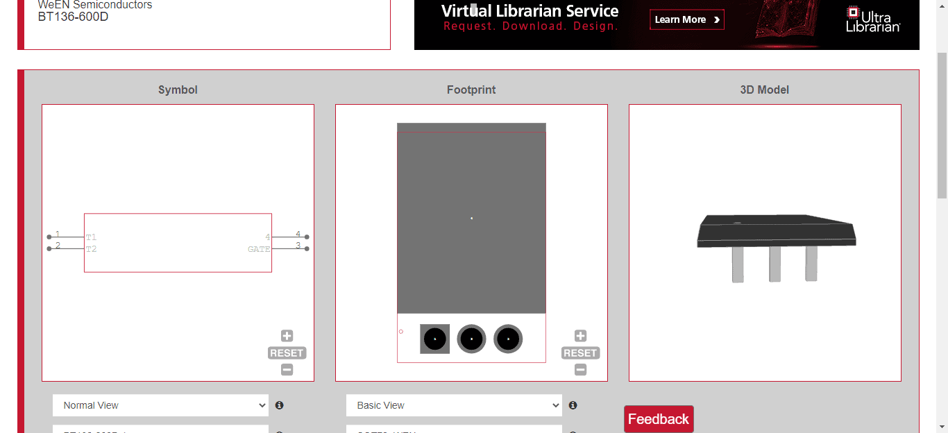
CAD file symbol and footprint for BT136-600D Triac from Ultra Librarian
Although the BT136 datasheet contains critical information for designing a circuit with this triac, there are times when a datasheet alone is not sufficient to create your circuit board design file for manufacturing. In those cases, you should look for free PCB footprints and schematic symbol databases online; such as Ultra Librarian, the world’s largest PCB CAD library.
If you’re looking for CAD models for common components, such as the device detailed in the BT136 datasheet, Ultra Librarian helps by compiling all your sourcing and CAD information in one place and providing downloadable model files for the most popular ECAD applications.
Working with Ultra Librarian sets up your team for success to ensure any design is going through production and validation with accurate models and footprints to work from. Register today for free.


