
There comes a point in every designer’s career where they receive a batch of assembled boards and none of them seem to work. What happens next is a long series of troubleshooting steps to try and locate the source of the problem. It’s natural to suspect that a faulty component is to blame, but this isn’t always the case.
If you know how to test electronic components and also understand when to administer these tests, you can save yourself a lot of time and headache. As we’ll see, it doesn’t always make sense to fully test electronic components, as some board failures can masquerade as component failures. Keep reading to learn how to test electronic components without creating excessive work for yourself.
When to Test Electronic Components
If you know anything about the electronics industry, you’ll know it is very risk-averse and tends to place high standards on quality. This means products at all levels will go through a battery of tests to ensure reliability and functionality. This includes semiconductor manufacturers and passive component manufacturers, which comprise nearly all the components in typical circuit boards.
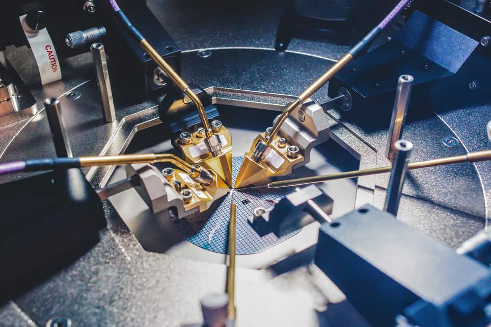
Semiconductor wafer with ICs undergoing testing
While components go through a battery of tests before they make it into your PCBA, there are some instances where additional testing is needed. These additional reliability tests or debug tests can help identify faulty components and assemblies, and designers can determine potential design changes that may be needed to ensure high reliability.
During Manufacturing
High reliability applications, such as aerospace and automotive systems, may require additional testing under various safety and industry standards. Some of these tests include:
- Thermal cycling and thermal shock testing
- HALT/HASS testing
- Burn-in testing
- Mechanical shock testing
These system-level tests are often used to identify failed PCBAs or individual components, and design changes can be recommended by your manufacturer. These tests are only cost-effective in high-volume manufacturing, so they are generally not performed during prototyping runs. More often, an individual designer will need to perform manual testing during board bring-up.
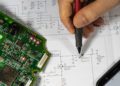
Testing During Debug and Board Bring-Up
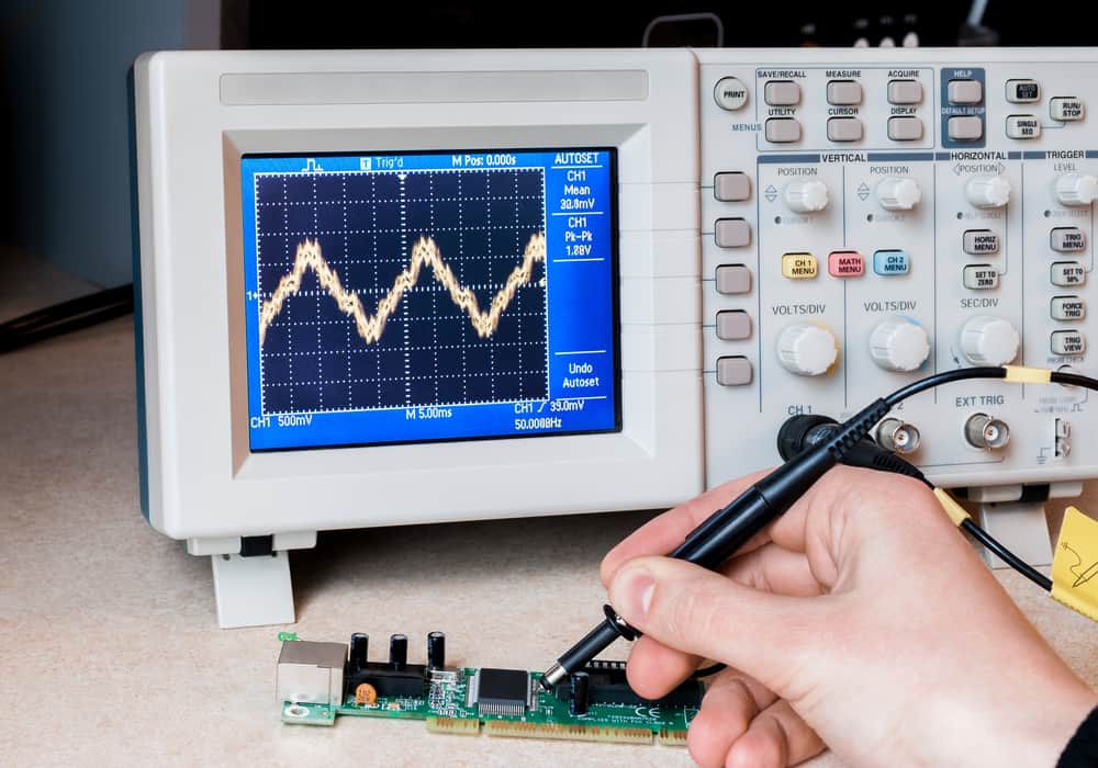
Board bring-up can be a nerve-wracking experience, especially when you start to suspect a component failure. Sometimes, when you’re working through debug tasks while working on a new board, you might narrow down a board failure to a potentially faulty component. You can certainly pull out your trusty multimeter and start taking some resistance measurements, but this is only useful for tracking voltage throughout the board. How can you test an electronic component once you’ve narrowed it down to a potential part failure?
In this case, unless the component was placed in a socket, the component is already soldered onto the board and will need to be removed. You won’t be able to do any probe-based tests directly when the component is on the board. Passives, transistors, electromechanical components (e.g., relays), connectors, and simple logic circuits can’t be properly tested with a multimeter to assess a component failure, and must be removed because every other feature on the board will become part of your test circuit. If you can remove the component, you can place it into an SMD test fixture or breadboard and check its electrical behavior with a test circuit or probe system.
Some on-board tests of a PCBA can be performed with a multimeter
Unfortunately, removing a component from the board is easier said than done. This is a sensitive task, as once you remove the component, you might not be able to re-solder it. For very small components, like 0402 passives, it can be difficult to pull the component off without leaving some leftover solder, which could bridge the pads on the board. For components with fine-pitch BGAs, you need to uniformly heat the component with a heat gun to pull off the component. You generally will not be able to easily re-solder the component if the part turns out to be working properly.
Keep these points in mind if you’re contemplating pulling components out the board and testing them manually, as you may end up needing to scrap the board entirely. Also, be sure to check the datasheet, as you may find graphs you can use to compare with your test measurements.
How to Test Electronic Components on Finished Boards
Although testing can involve many complex procedures, particularly with ICs, there are some simple steps a designer can take to ensure their board was fabricated correctly and there are no component defects:
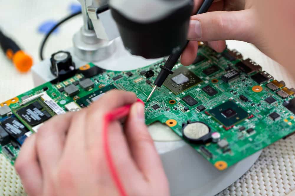
- Visual inspection: Look over the entire board for any signs of damaged components. Also, watch for any ICs with discolored or melted packaging. This may require a magnifying glass or microscope.
- Component power test: Power up the board and use a voltmeter to measure the voltage reaching the components. Sometimes, an apparent component failure is a simple matter of poor power distribution. You might need to look up PCB footprints for your components to ensure you’re checking the right pins.
- Power distribution test: In addition to measuring the power reaching components, you can check the voltage at various points in your power tree with a multimeter. Make sure you measure with respect to the correct ground point to ensure safety and accuracy.
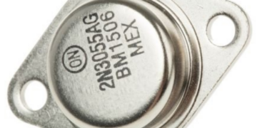
- Bipolar transistor measurements: You can use a voltmeter to measure the built-in voltage of BJTs on the board by connecting the meter to the collector and emitter. This is usually ~100 mV for small transistors.
Points 2 and 3 in the above list are normally checked during in-circuit testing, which can be requested from a manufacturer. It carries some programming costs, so it might be better to do this in-house if you’re only producing a small run or you’re building prototypes. More specialized tests, such as signal integrity tests or logic tests, may require specialized equipment not used by all PCB manufacturers. If you’re scaling from a prototype to full-scale production, keep testing requirements in mind as you work with your manufacturer to start production.
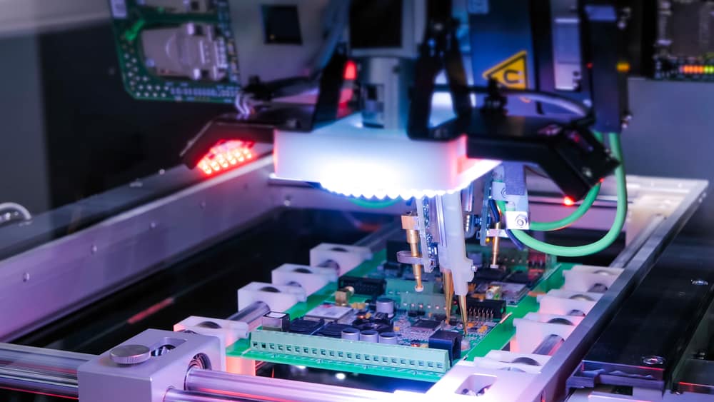 In-circuit testing is known to identify over 95% of defects requiring rework during manufacturing
Use Verified Component Data for Testing
If you’re learning how to test electronic components and you need to make sure you have correct parts data, try using the electronics search engine features in Ultra Librarian. You’ll be able to access verified sourcing information and CAD data that is compatible with popular ECAD applications, which will help you streamline your verification process.
Working with Ultra Librarian sets up your team for success to ensure streamlined and error-free design, production, and sourcing. Register today for free.
