

In the world of microcontrollers, there are a few components that have dominated the market and become immensely popular. Components like the Atmel ATMega328P, STM32, and ESP32 have all found their place among makers and professional designers in the embedded ecosystem. Additionally, there is one up-and-coming component that provides the same ease of use as these components with production-grade specifications: the MSP430. This popular line of microcontrollers from Texas Instruments offers a range of specifications and capabilities, but it operates with a single IDE and SDK, making an embedded developer’s life much easier.
If you’ve never considered using an MSP430 microcontroller as the main processor for your embedded system, we’ve prepared a short guide to help you get started. We’ll cover a bit of the setup that needs to happen on the board and the resources you need to start developing firmware for your device.
Getting Started With MSP430 Microcontrollers
MPS430 microcontrollers are RISC-based low-power, low-profile MCUs intended for a range of embedded applications. While they don’t pack the computing power of a large FPGA or other TI processors like Sitara, they meet performance requirements for many embedded systems applications involving data acquisition and lightweight computing.
| Data bus width | 8, 16, or 32 bits |
| Total RAM | Up to 128 KB (SRAM + FRAM in some models) |
| Flash memory | Up to 512 KB |
| Max. clock speed | Up to 25 MHz |
| Digital interfaces | SPI, I2C, USB, UART |
| Analog interfaces | Capacitive touch sense interface, comparator, up to 24-bit ADC |
| Special interfaces | 5 V and 1.8 V tolerant I/Os |
| Packaging | Through-hole or SMD options |
While previous components only had up to 66 KB RAM, newer models have more RAM (up to 128 KB) and specialized features such as a proprietary capacitive touch sensing interface. If you’ve decided to use an MSP430 microcontroller, you’ll need to consider some points in the board design and how you’ll work in your development environment.
Board Design
Prototyping boards that are used to support an MSP430 need to be designed to support either in-house programming, on-the-line programming, or both. Texas Instruments microcontrollers generally use a 3-pin or 4-pin interface for programming a device. On smaller MSP430 variants, such as the MSP430Fxxxx series in DIP packages, the interface is shared with JTAG due to the small pin count on these boards. For other variants with higher pin count, there may be dedicated GPIO pins that are used for configuration and flashing. Look for the pin assignments in your datasheet.
Once you’ve determined pin assignments, you can connect pin headers so that the component pins can be accessed with a configuration adapter. This is normally done with a 10-pin or 14-pin ribbon cable that matches to a male connector. An example shrouded 10-pin header is the Wurth 61201021621 (see below). In addition to a pin header for flashing, designs may also require placing power and ground connections on a certain set of pins, called sense-on-power (SOP) pins. These are GPIOs that are brought up to the core logic level or grounded to put the device in a specific configuration mode for flashing. These can be set to PWR or GND with jumpers or 0 Ohm resistors.
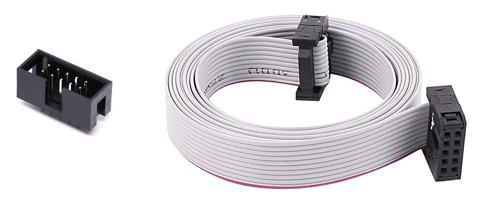
10-pin header and ribbon cable
The above ribbon cable and connector can be used to connect to an MSP430 Launchpad board or a programmer adapter for in-house prototyping and application testing. For flashing on the production line, all pins can be accessed with probes on testpoint pads or with a cable connector to a pin header on the assembled board. If you need production line flashing, make sure to contact your assembler to learn about their process and design your board accordingly.
Application Development
Embedded systems developers will need to create an application for their program in C/C++. Texas Instruments provides several tools to help application developers compile code to binaries, flash code to the board, and interface with a testing environment. Some of the basic tools developers need include:
- MSPWARE: includes all peripherals needed to develop and flash firmware to MSP430 microcontrollers (download here).
- Code Composer Studio: an integrated development environment (IDE) for all Texas Instruments products (download here).
- Uniflash: a flashing utility used to interface with an evaluation board (Launchpad product), MSP-GANG programmer via RS-232 or USB, or MSP-FET programmer via USB/14-pin ribbon cable (download here).
Although not officially supported by Texas Instruments, there is an implementation of MSP430 libraries in Python that can be used to create a GUI or console application on a workstation. This application can then be used to communicate with your embedded board for data acquisition and testing. Other desktop languages can be used to interface with an MSP430-enabled board over serial communication interfaces (usually USB-to-UART).
Find Your Footprints From a Verified Partner
Even though packaging for MSP430 microcontrollers is standardized, designers will need footprints before building a board. If you’re not in the mood to create footprints for your components, make sure you use an electronics search engine to find footprints and sourcing data from major distributors. With today’s supply chain volatility, it pays to have all this data in one.
When you need to find electrical data and ECAD models for MSP430 microcontrollers and other components for embedded systems, try using the electronics search engine features in Ultra Librarian. All ECAD data you’ll find on Ultra Librarian is compatible with popular ECAD applications and will help you streamline your design process. You’ll also find datasheets and sourcing information from major distributors.
Working with Ultra Librarian sets up your team for success to ensure streamlined and error-free design, production, and sourcing. Register today for free.


